Commence Building
-
Blunt Force Trauma
- Senior member
- Posts: 666
- Joined: Tue Jan 25, 2005 10:18 pm
- I've played Bz for: Forever
- Dm Strat or Missions: DM
- Location: North Carolina
Re: Commence Building
After all that work, I would have thought they would have at least gone to about 300 feet to launch.
"To learn who has no confidence in their convictions, simply find out who you are not allowed to criticize"
~Voltaire
-
Dx.

- Admin
- Posts: 793
- Joined: Wed Jul 02, 2008 8:47 am
- I've played Bz for: 20 years
- Dm Strat or Missions: MPI
Re: Commence Building
The rocket camera is great, what a view.
All truth goes through three stages:
•First it is ridiculed
•Then it is violently opposed
•Finally it is widely accepted as self evident
-Arthur Schopenhauer
•First it is ridiculed
•Then it is violently opposed
•Finally it is widely accepted as self evident
-Arthur Schopenhauer
-
FirBirGir
- Admin
- Posts: 529
- Joined: Wed Jul 12, 2006 12:28 am
- I've played Bz for: 10+ Years
- Dm Strat or Missions: Both
- Contact:
Re: Commence Building
That may be why they didn't go high before launching, they wanted to recover the rocket and camera. The chute can drift for miles if it gets too high...
-
hitchcockgreen

- Senior member
- Posts: 1422
- Joined: Thu Mar 03, 2005 11:01 pm
- I've played Bz for: a bunch.
- Dm Strat or Missions: strat and ia
- Location: The Frozen Wastes of Canada
-
Dx.
- Admin
- Posts: 793
- Joined: Wed Jul 02, 2008 8:47 am
- I've played Bz for: 20 years
- Dm Strat or Missions: MPI
Re: Commence Building
Drop the camera/rocket with GPS in someones backyard and you'll have more trouble than trying to get it back.
All truth goes through three stages:
•First it is ridiculed
•Then it is violently opposed
•Finally it is widely accepted as self evident
-Arthur Schopenhauer
•First it is ridiculed
•Then it is violently opposed
•Finally it is widely accepted as self evident
-Arthur Schopenhauer
-
hitchcockgreen
- Senior member
- Posts: 1422
- Joined: Thu Mar 03, 2005 11:01 pm
- I've played Bz for: a bunch.
- Dm Strat or Missions: strat and ia
- Location: The Frozen Wastes of Canada
-
hitchcockgreen
- Senior member
- Posts: 1422
- Joined: Thu Mar 03, 2005 11:01 pm
- I've played Bz for: a bunch.
- Dm Strat or Missions: strat and ia
- Location: The Frozen Wastes of Canada
Re: Commence Building
The next step....
Sent from my SAMSUNG-SGH-I747 using Tapatalk
Sent from my SAMSUNG-SGH-I747 using Tapatalk
- Attachments
-
"Unthinking respect for authority is the greatest enemy of truth." -Albert Einstein
-
Dx.
- Admin
- Posts: 793
- Joined: Wed Jul 02, 2008 8:47 am
- I've played Bz for: 20 years
- Dm Strat or Missions: MPI
Re: Commence Building
Making new limbs to replace blown up ones?
All truth goes through three stages:
•First it is ridiculed
•Then it is violently opposed
•Finally it is widely accepted as self evident
-Arthur Schopenhauer
•First it is ridiculed
•Then it is violently opposed
•Finally it is widely accepted as self evident
-Arthur Schopenhauer
-
hitchcockgreen
- Senior member
- Posts: 1422
- Joined: Thu Mar 03, 2005 11:01 pm
- I've played Bz for: a bunch.
- Dm Strat or Missions: strat and ia
- Location: The Frozen Wastes of Canada
Re: Commence Building
Guess the board doesn't like animated gifs.
Let's see if this works:

Let's see if this works:
"Unthinking respect for authority is the greatest enemy of truth." -Albert Einstein
-
Dx.
- Admin
- Posts: 793
- Joined: Wed Jul 02, 2008 8:47 am
- I've played Bz for: 20 years
- Dm Strat or Missions: MPI
Re: Commence Building
Well not 2MB ones, the setting is 300KiB max for all images.
All truth goes through three stages:
•First it is ridiculed
•Then it is violently opposed
•Finally it is widely accepted as self evident
-Arthur Schopenhauer
•First it is ridiculed
•Then it is violently opposed
•Finally it is widely accepted as self evident
-Arthur Schopenhauer
-
Blunt Force Trauma
- Senior member
- Posts: 666
- Joined: Tue Jan 25, 2005 10:18 pm
- I've played Bz for: Forever
- Dm Strat or Missions: DM
- Location: North Carolina
Re: Commence Building
Not sure I buy that. Unless the quads are taking the impulses for a general directional movement command, and the quads are 95% flying themselves. And certainly not staying in formation that well without the majority of flight control being automated.
Oh, and while I'm here. . . my next project. . .
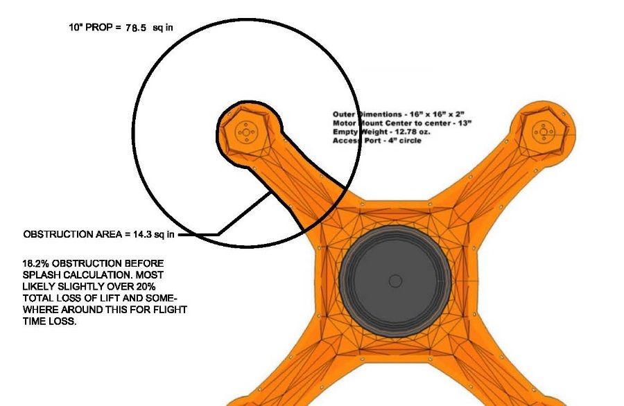
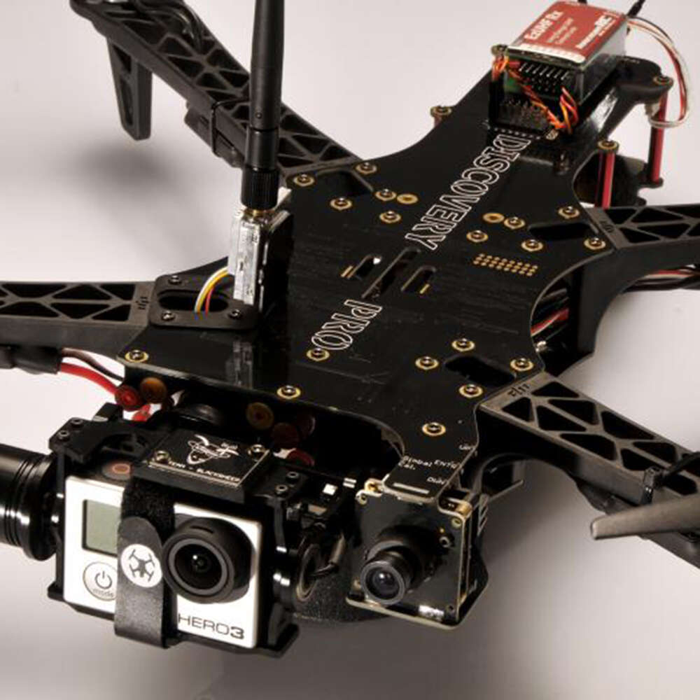
I've always been bothered by the lock-step all DYI builders, and all commercial multirotors have in common, in that unless the booms are round or small and square (such as both my carbon fiber MRs), all booms are laid horizontal. Being flat against the thrust column makes them inherently less efficient, such as the popular Team Black Sheep quad. Or this kick-starter fund-raiser is promoting an "indestructible" quad made out of high-impact plastic. The amount of thrust column obstruction is very high, essentially removing 20% of its lift capability.
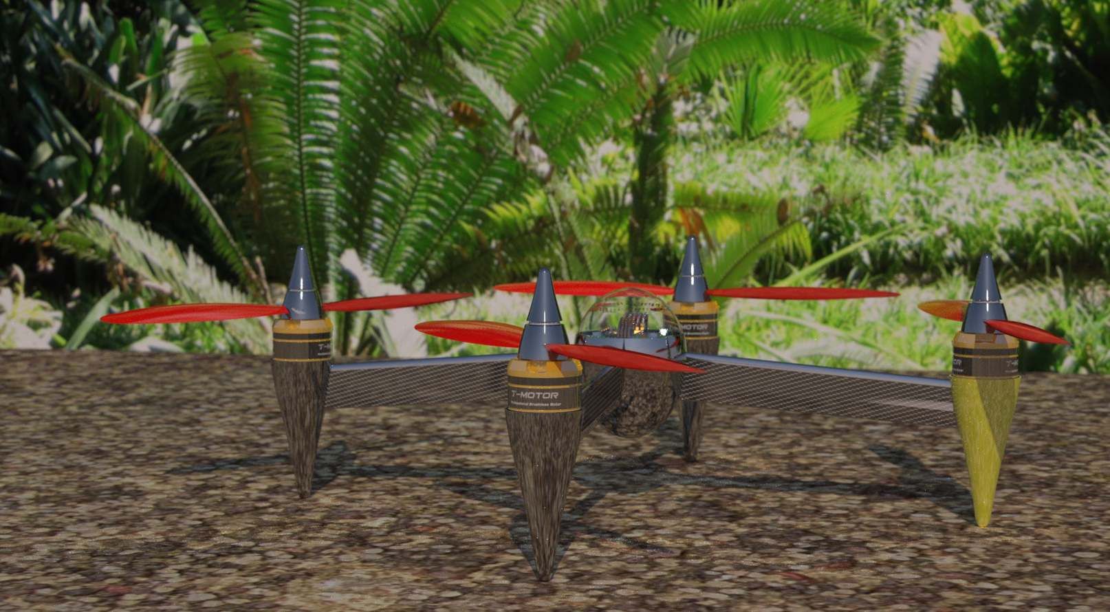
My next multirotor is a step towards the 'racing quad' I modeled a few months back. It has almost no thrust column obstruction, somewhere around 4%.
It's made from 5/32" and 3/16" plywood and is proof of concept. If it flies well, I'll reproduce it with 1.5mm and 2mm carbon fiber or G10 plate. That will allow the center plate rings to be narrower and the booms to have less height, as well as making it more stiff and shedding about 40-50% of the frame's mass, and reducing the T.C.O. to around 3.5%. Since there's a motor under the thrust column, it's impossible to get much under 3%. But what it does do is reduce the splash obstruction to virtually zero.
Oh, and while I'm here. . . my next project. . .
I've always been bothered by the lock-step all DYI builders, and all commercial multirotors have in common, in that unless the booms are round or small and square (such as both my carbon fiber MRs), all booms are laid horizontal. Being flat against the thrust column makes them inherently less efficient, such as the popular Team Black Sheep quad. Or this kick-starter fund-raiser is promoting an "indestructible" quad made out of high-impact plastic. The amount of thrust column obstruction is very high, essentially removing 20% of its lift capability.
My next multirotor is a step towards the 'racing quad' I modeled a few months back. It has almost no thrust column obstruction, somewhere around 4%.
It's made from 5/32" and 3/16" plywood and is proof of concept. If it flies well, I'll reproduce it with 1.5mm and 2mm carbon fiber or G10 plate. That will allow the center plate rings to be narrower and the booms to have less height, as well as making it more stiff and shedding about 40-50% of the frame's mass, and reducing the T.C.O. to around 3.5%. Since there's a motor under the thrust column, it's impossible to get much under 3%. But what it does do is reduce the splash obstruction to virtually zero.
"To learn who has no confidence in their convictions, simply find out who you are not allowed to criticize"
~Voltaire
-
hitchcockgreen
- Senior member
- Posts: 1422
- Joined: Thu Mar 03, 2005 11:01 pm
- I've played Bz for: a bunch.
- Dm Strat or Missions: strat and ia
- Location: The Frozen Wastes of Canada
Re: Commence Building
"Unthinking respect for authority is the greatest enemy of truth." -Albert Einstein
-
Dx.
- Admin
- Posts: 793
- Joined: Wed Jul 02, 2008 8:47 am
- I've played Bz for: 20 years
- Dm Strat or Missions: MPI
Re: Commence Building
Insect like robots, cool.
All truth goes through three stages:
•First it is ridiculed
•Then it is violently opposed
•Finally it is widely accepted as self evident
-Arthur Schopenhauer
•First it is ridiculed
•Then it is violently opposed
•Finally it is widely accepted as self evident
-Arthur Schopenhauer
-
Blunt Force Trauma
- Senior member
- Posts: 666
- Joined: Tue Jan 25, 2005 10:18 pm
- I've played Bz for: Forever
- Dm Strat or Missions: DM
- Location: North Carolina
Re: Commence Building
Please excuse the "inside baseball" references, this is from an RC forum I posted to...
There’s been one aspect of all multirotors that has nagged me for some time.
And that is the insouciant concern for thrust column efficiency (TCE). Most builders take little notice of TCE, in that they design and build mostly for a handful of other reasons. Several commercial multirotors designers ignore this aspect as well. Many designers concern themselves with a single or combination of, initial cost, crash repair cost, crash management, size, weight, payload capacity, materials at hand, what they’ve seen before, etc. Rarely, if ever, is TCE even a consideration.
This is surprising in that low TCE can reduce flight time and lift capacity by as much as 25%. Most plate-type booms are in the neighborhood of 15%. Many configurations aggravate the TCE by placing the ESC flat, directly in the highest cross-section of thrust. Many place holes in the booms, however that most likely for weight reduction, and the result is turbulence, buying very little increased lift.
But to give credit where credit is due, clean carbon fiber round booms have outstanding TCE. But I suspect CF tubes are chosen mostly for weight/strength consideration. However, even square wood, aluminum or carbon fiber booms have decent efficiency. Square booms do have a maximum thrust splash area, in that the leading edge is flat, but since a square tube or solid boom has a relatively small planform area, the thrust splash does not move into a critical region of gross inefficiency overall. I have seen double plates turned vertical, but generally the boom has horizontal structure between the plates, such as screws, standoffs, etc., to improve rigidity.
So, setting aside those designs which are either excellent or passable in TCE, I want to experiment with a paradigm shifting idea. To step beyond even the round clean carbon fiber boom, and get the TCE as close to 100% as is possible, by turning the grossly inefficient common flat boom vertical.
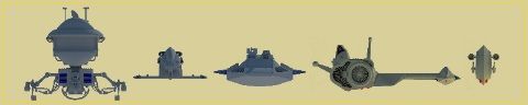
The idea was sparked by my ‘Racing Quad’ design I did several months ago. It basically utilized a shallow chord airfoil shape as the booms. It then occurred to me, if the boom could be made stiff enough, a simple flat plate could be used and could be built much easier and cheaper. So I began to design from that aspect.
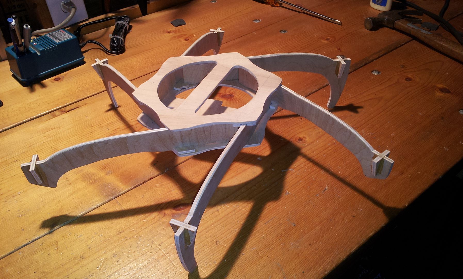
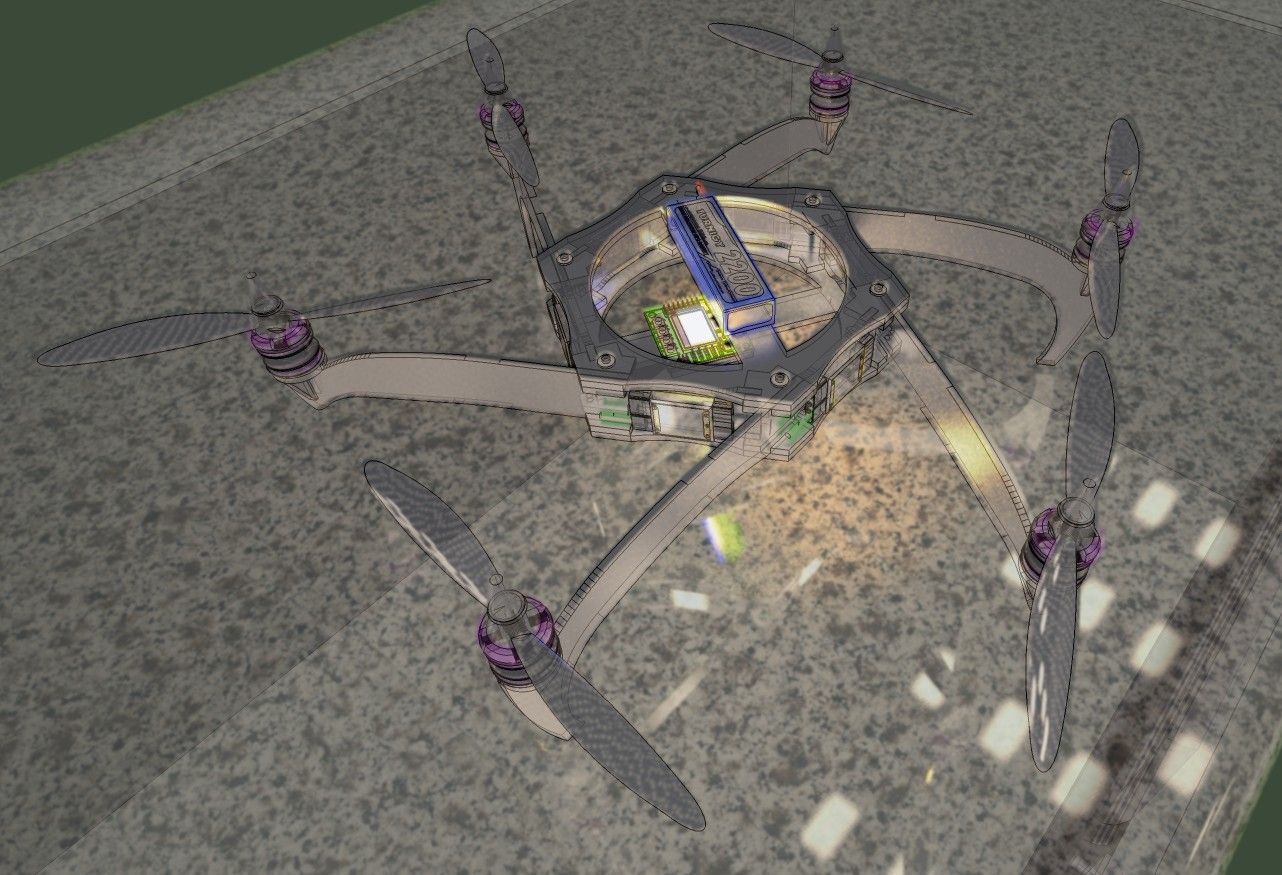
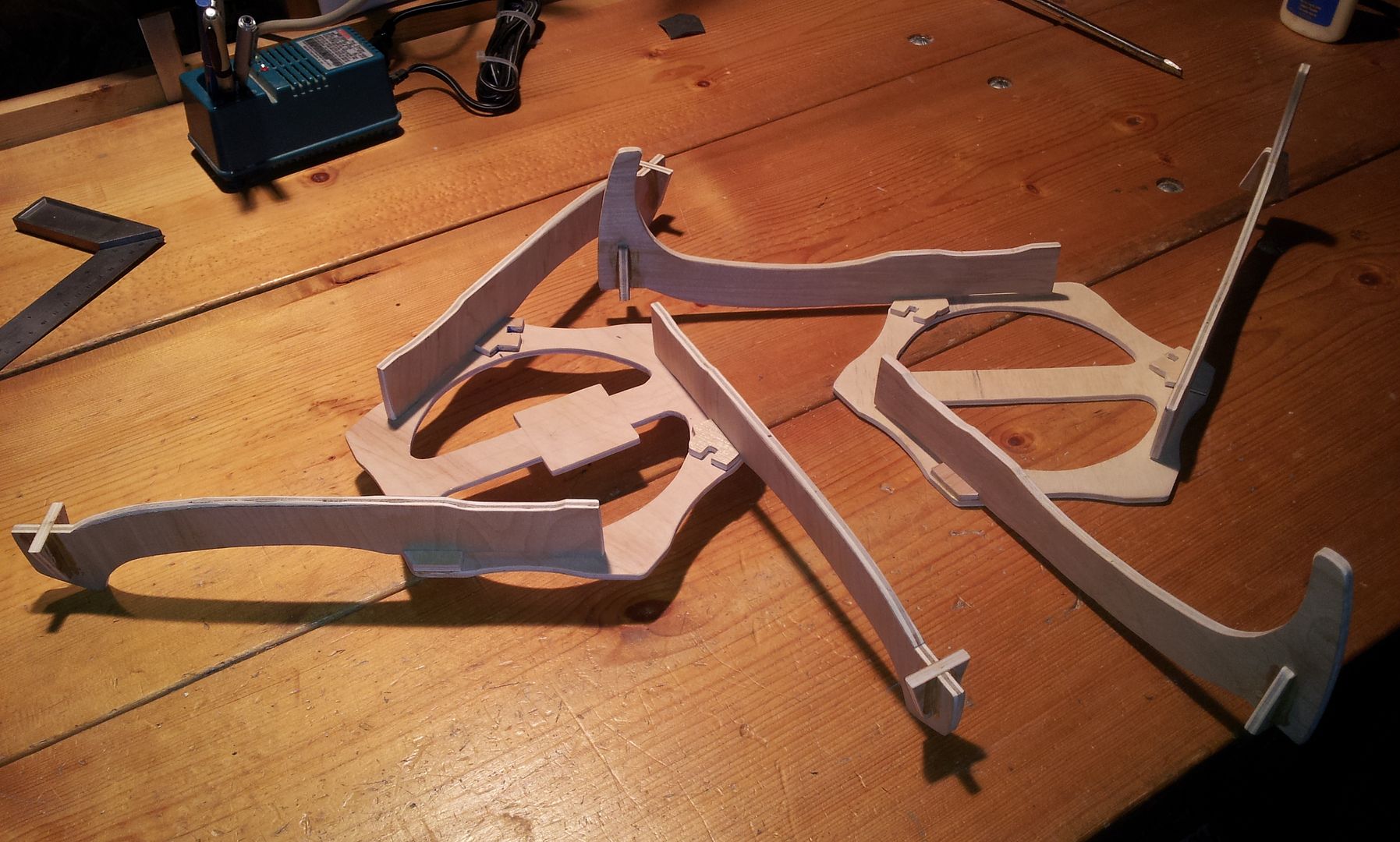
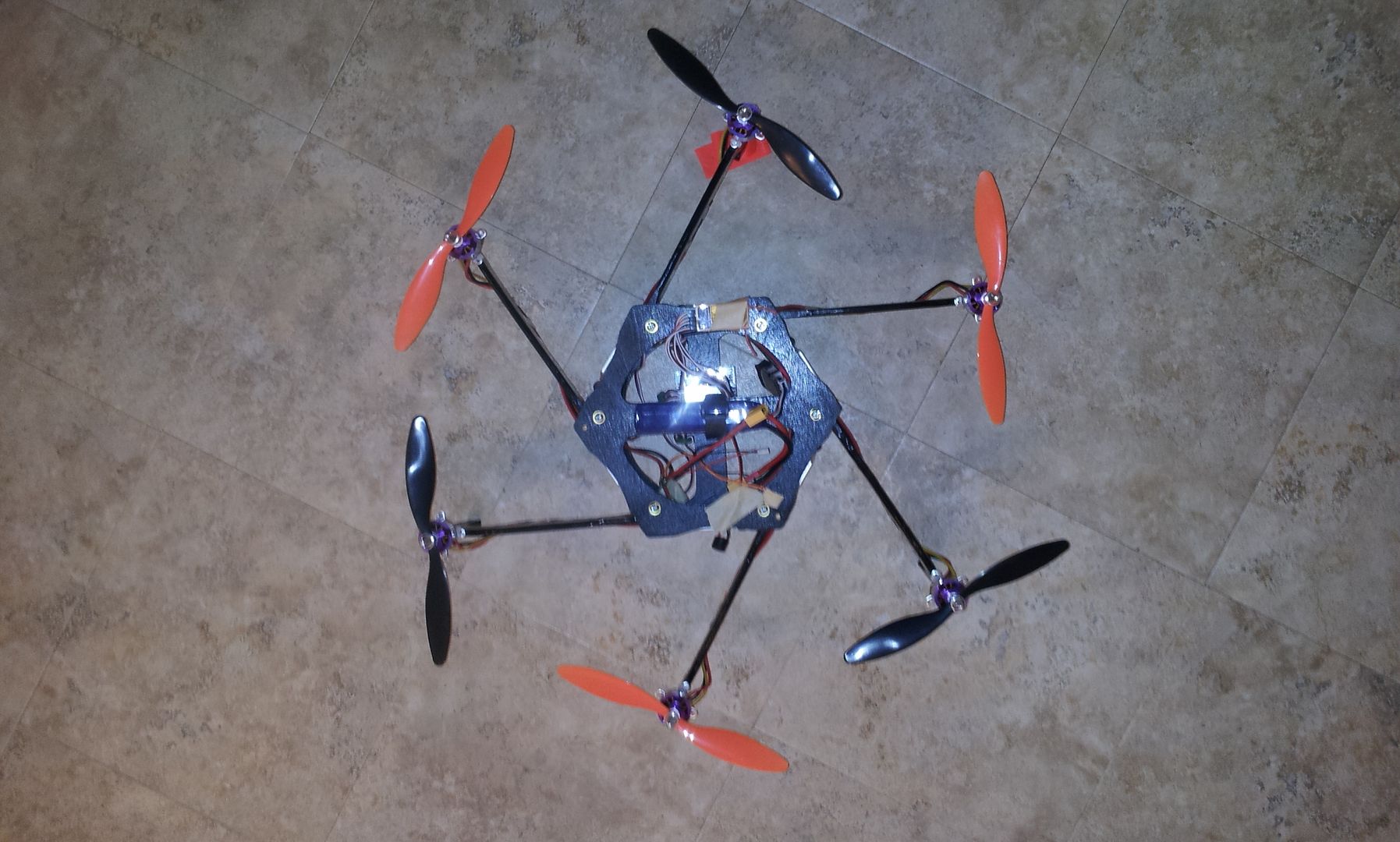
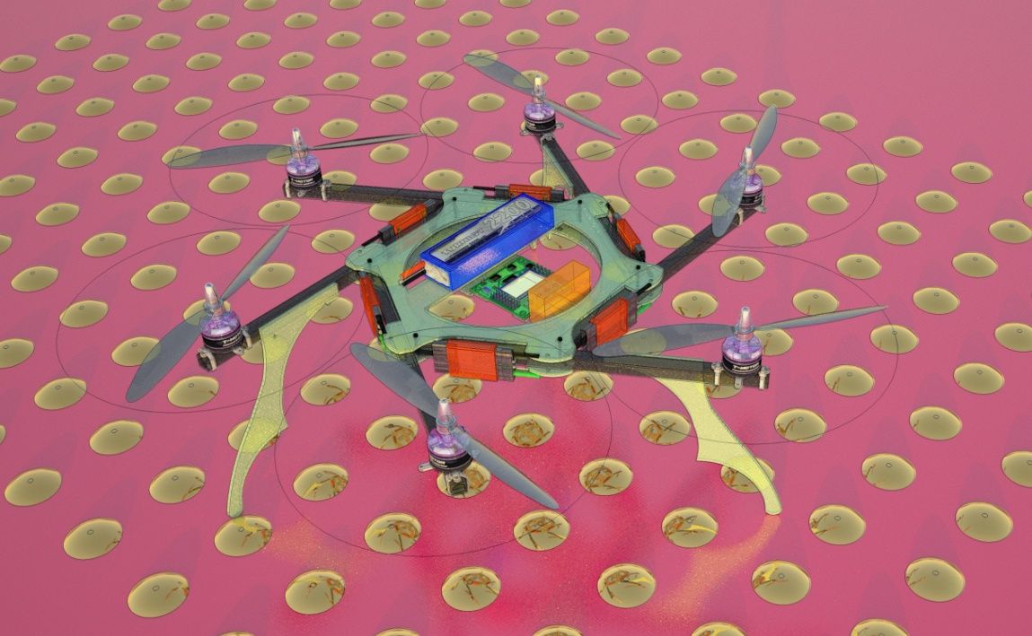
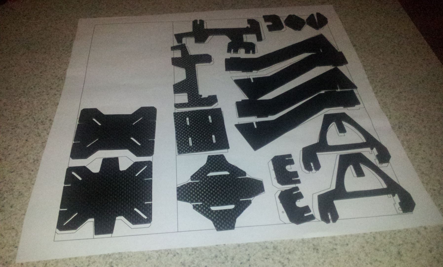
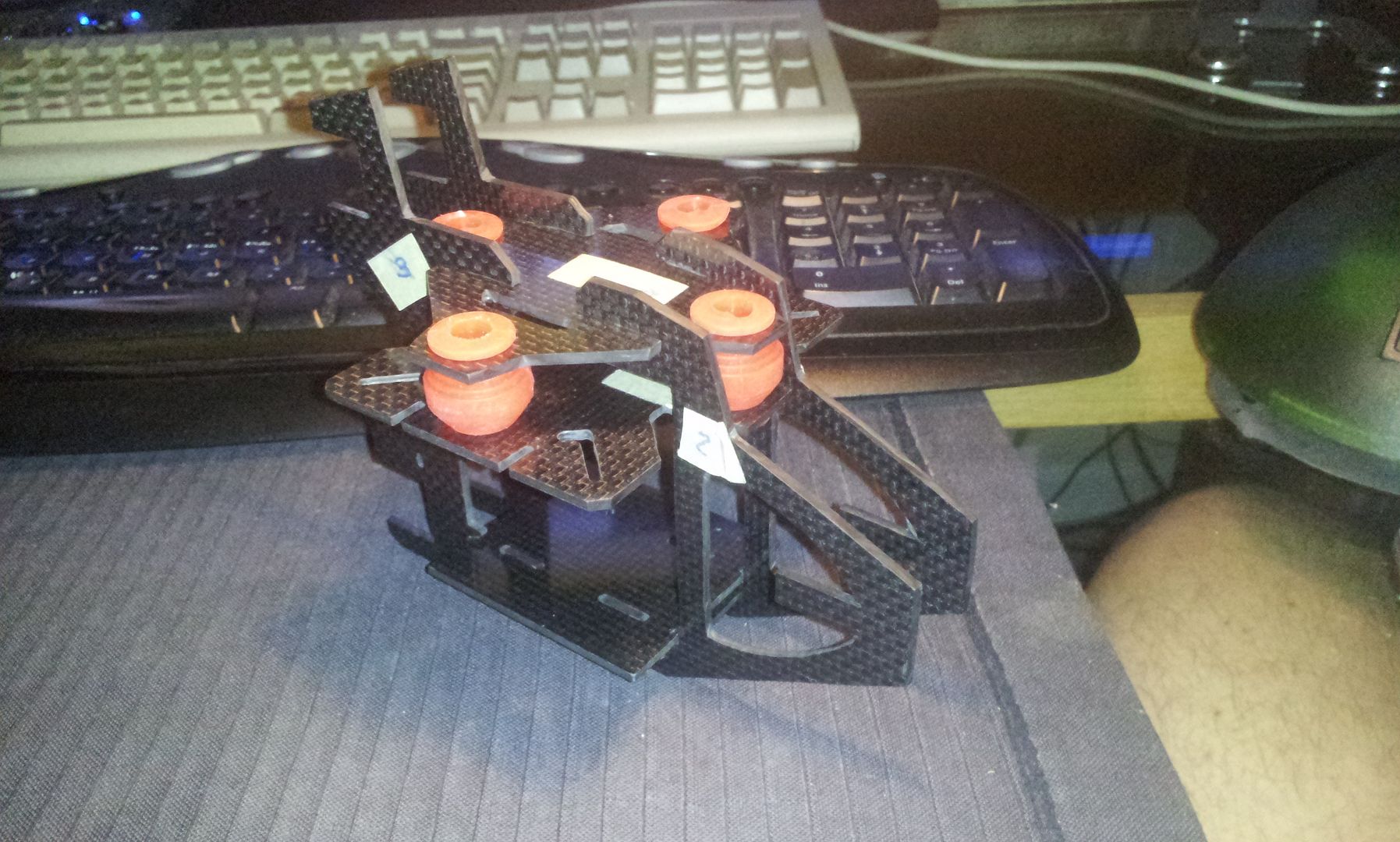
The following hexicopter is made from 3/16” plywood for the booms and 5/32” plywood for the main plates.
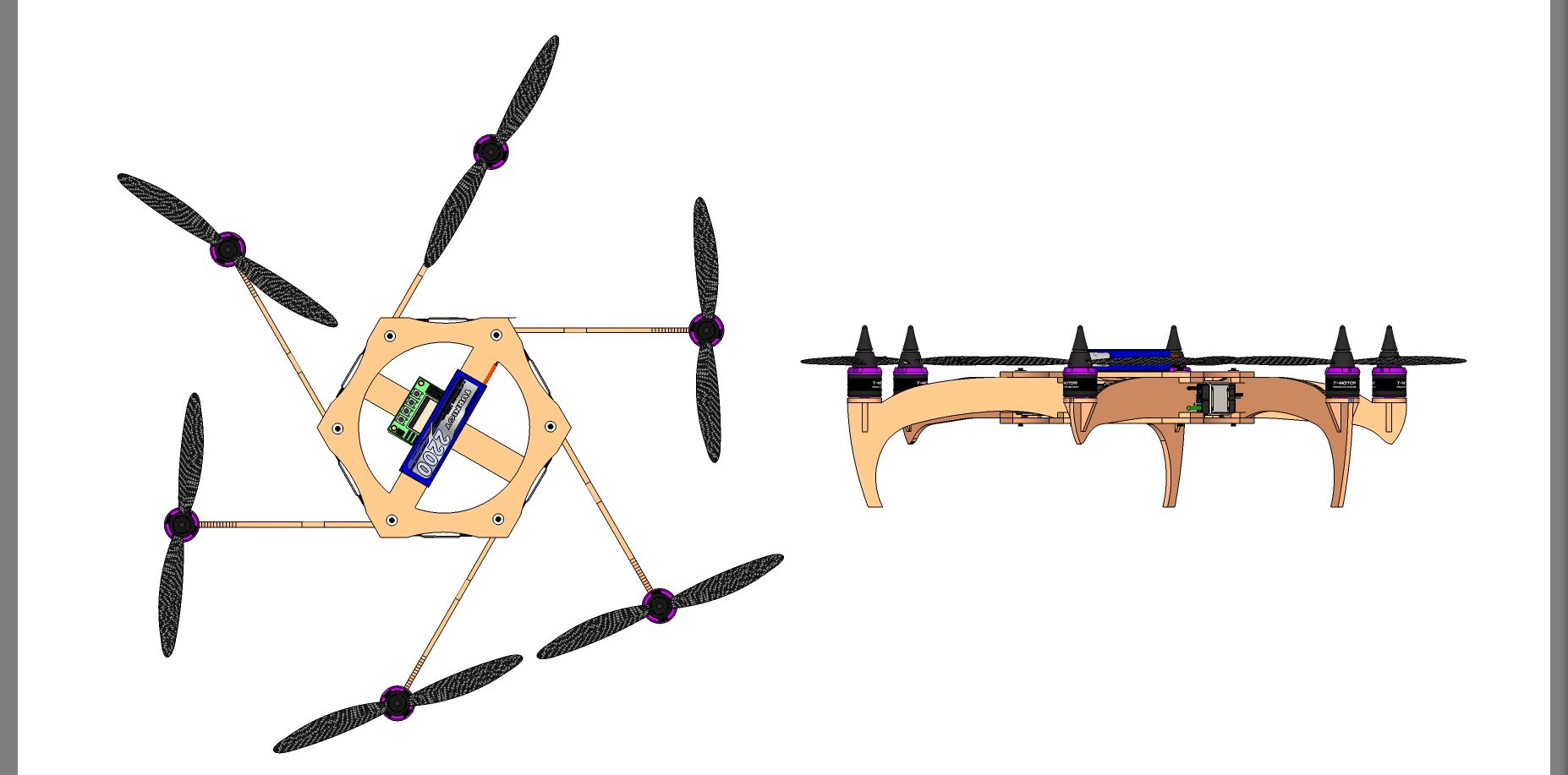
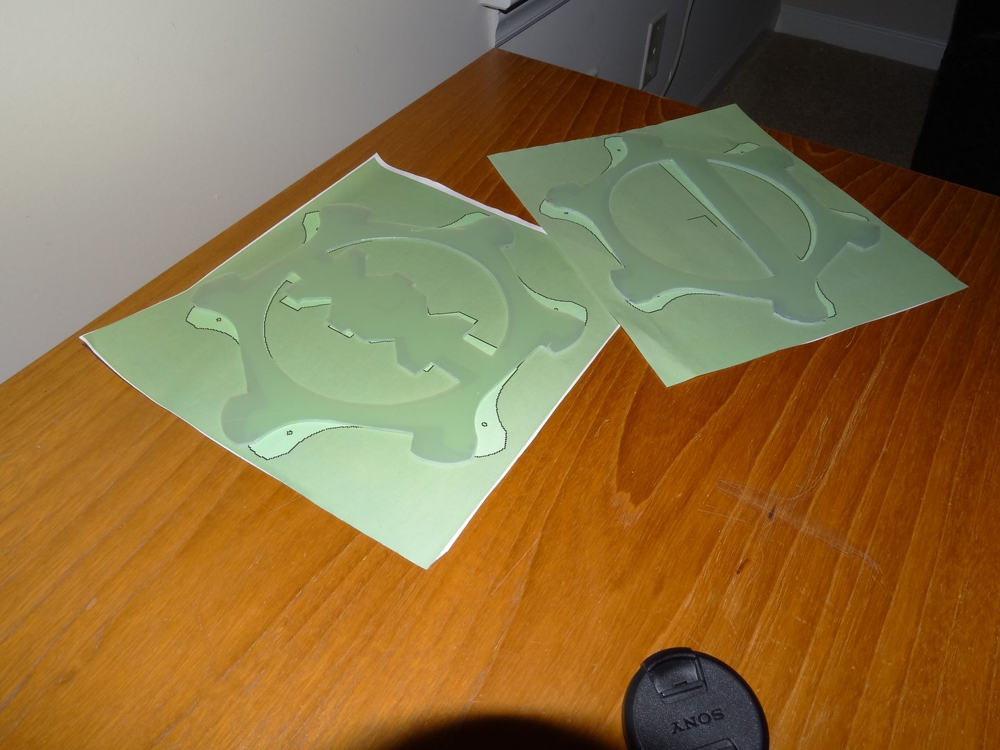
I started by designing my general idea in SketchUp, then tweaking and changing several times until I had a rough structure, then trimmed the main plate and booms down to a size that was not too overly bulky given I was using an average strength material. I then printed out the shapes and spray adhered them to the plywood and cut them out with a band saw.
I coated the area of most active boom flex with epoxy, essentially adding a ~0.6mm non-reinforced rigid membrane tube.
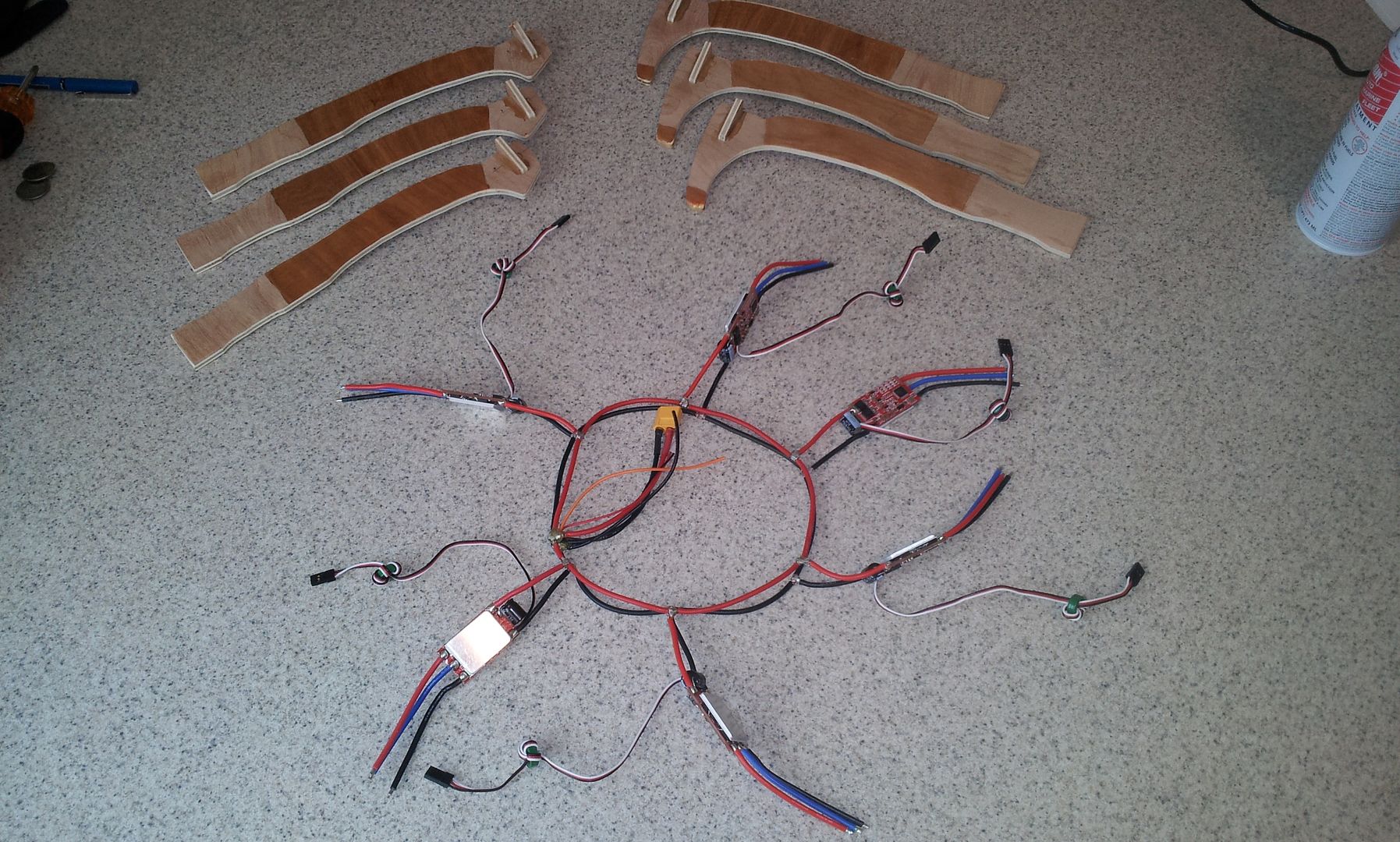
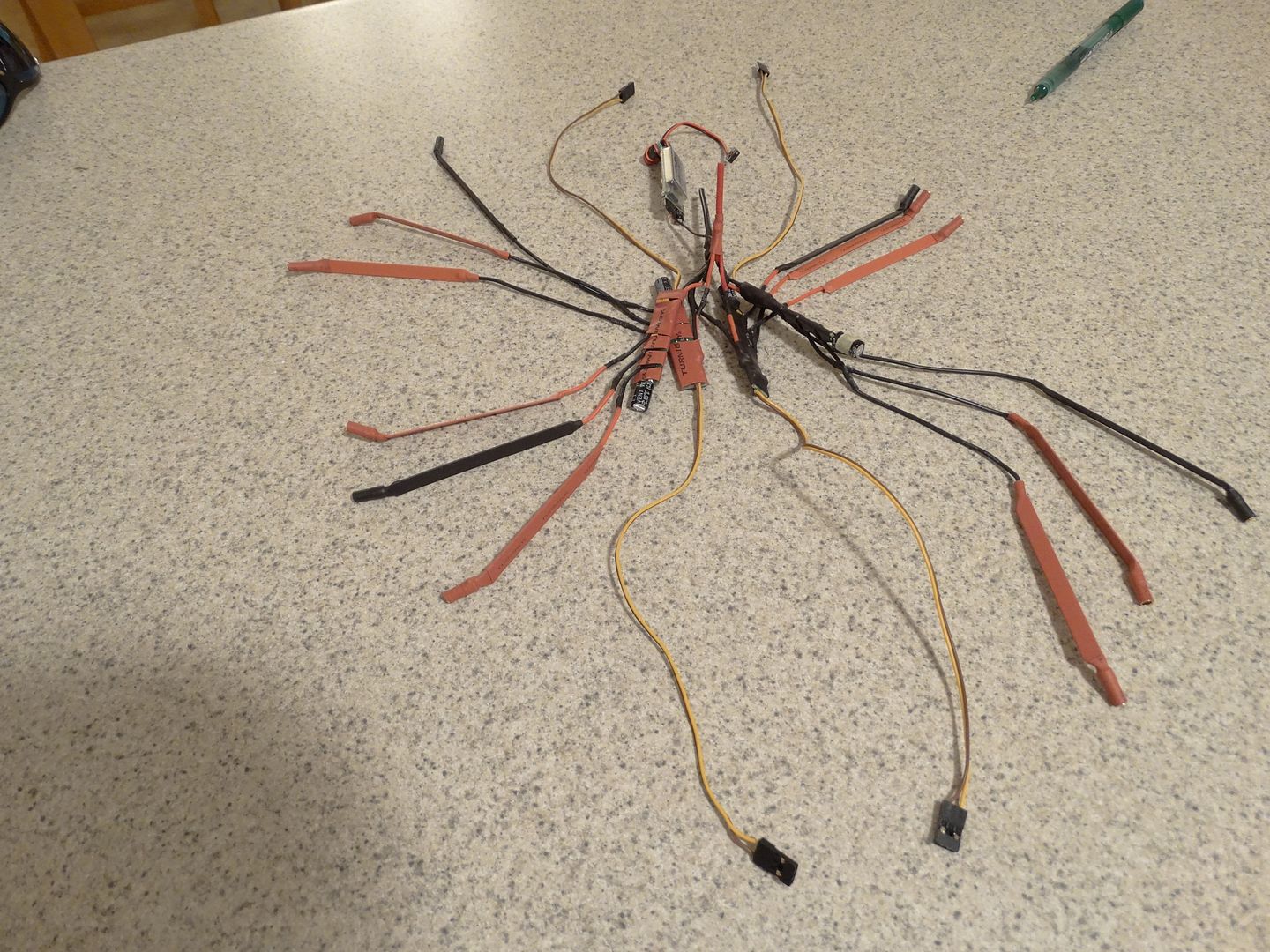
I made a common ring-type harness. All connections are splayed wire T interface connections with a fine copper wire wrapping, then soldered and double coated with epoxy.
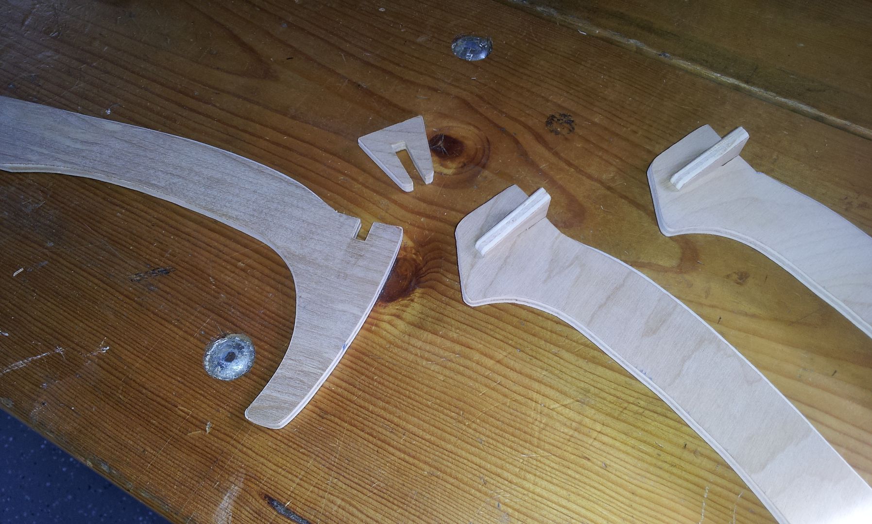
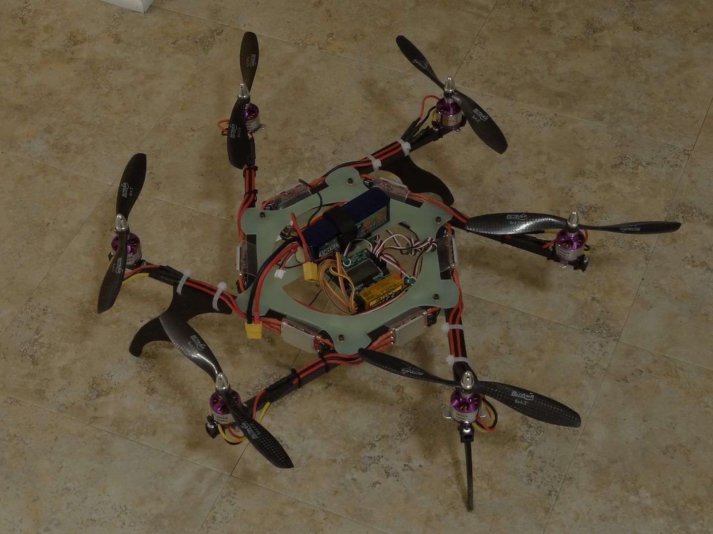
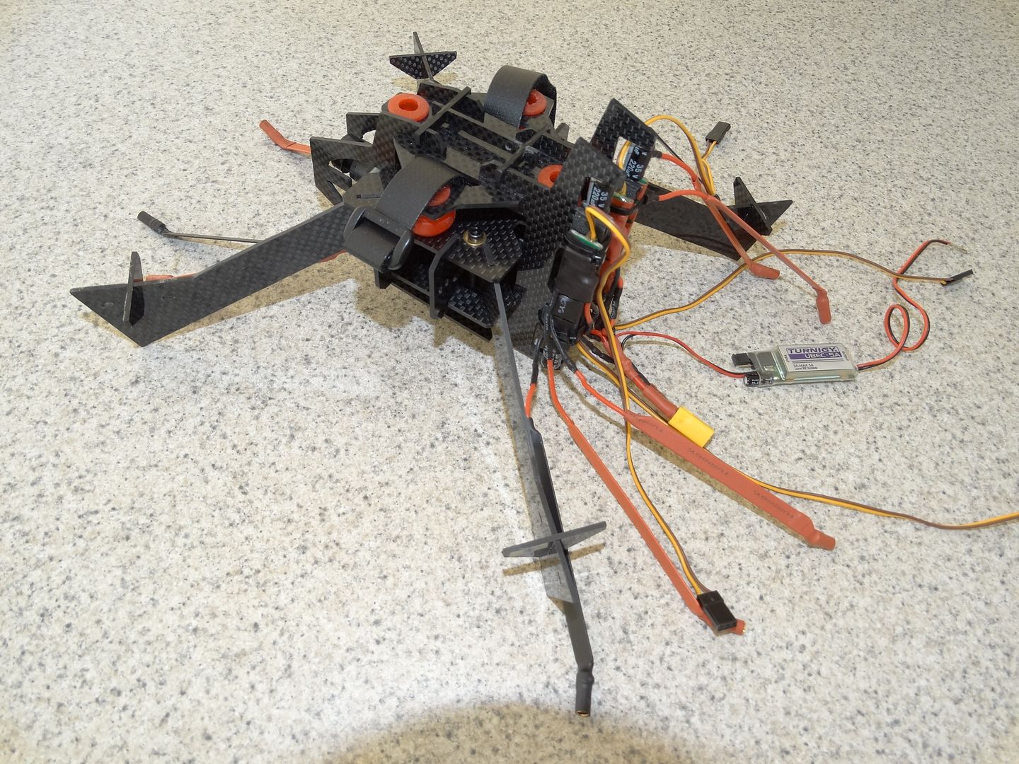
I suspect the reason why this design has not been done before, (at least I have yet to see it) is the problematic mounting of the motors on a very thin vertical plate. My solution is straightforward and simple. I used interlocking pieces, wood glued the pieces and reinforced them with two coats of epoxy on the surface. I also did not use the cross piece to zip-tie the motors down. They are only for lateral support, so there is no constant upward pull, or jerk moments on the piece, only compression.
Mounting the vertical booms to the frame is easy. I made blocking tabs and guides at every other corner, and did the same on the opposing plate, offset by a corner, so all corners have blocking and guide rigidity either above or below.
The two halves apart that are pressed together and securely clamped with six screws.
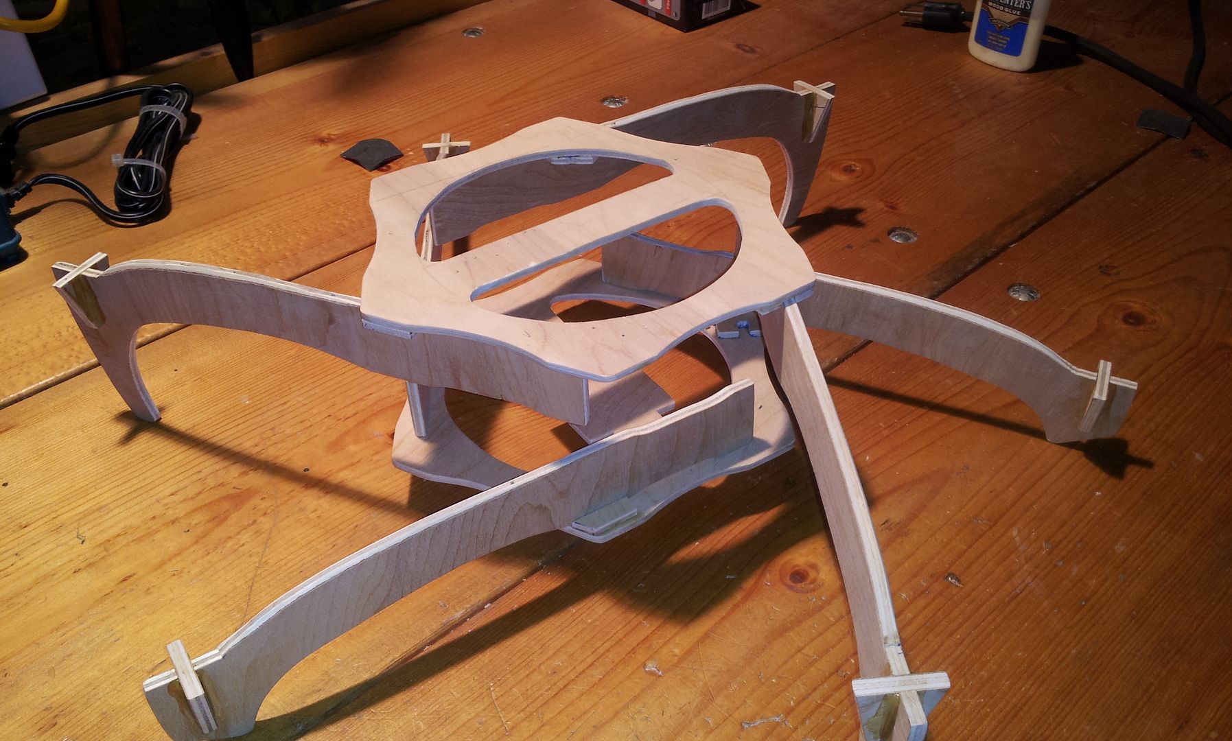
The result is an amazingly strong and rigid six sided box structure that can withstand dozens of kilos of shear, trapezoidal force.
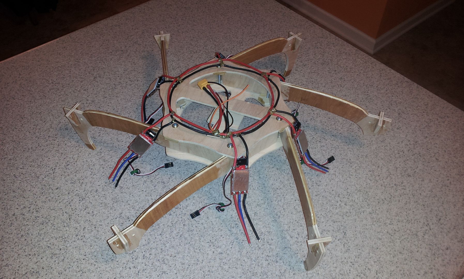
I’m also utilizing clear shrink as my ESC mounting material. I’ve indented the booms so that the shrink does not interfere with the clamp region near each fastener, and to allow higher PSI at the clamp points and to allow the shrink to move freely during the heating process.
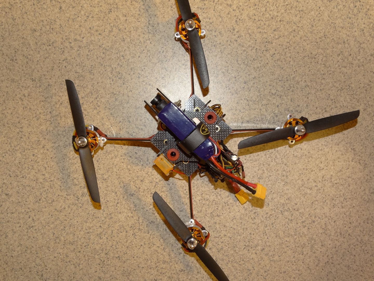
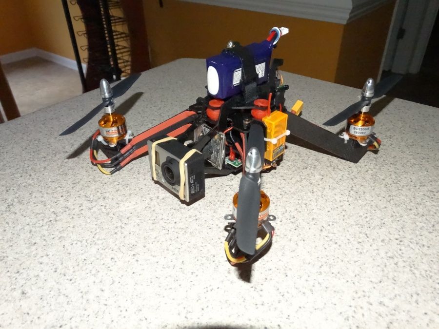
I’ve recessed the KK2.1 ‘inside’ the ring for protection and also recessed it back, off center about 20mm, so the Invensense chip is as close to the center of lift and the CG as possible. The battery is mounted on top to put the elevation CG closer in-line with the lift plane. The result is the elevation CG is about 1cm below the lift plane. I mounted the Rx underneath since I used foil tape to afix the motor wires to the booms. Foil tape is extremely strong in uniform tension, but yields easily when tearing.
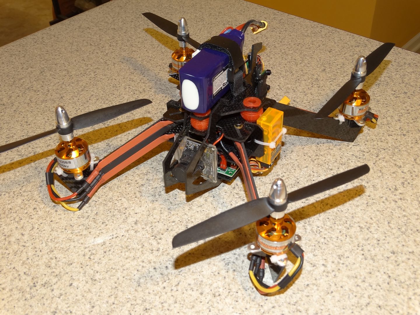
Next came some rattle-can black and putting it together. Both went fast. I was a little worried I would need three hands to wrestle to manipulate it all, but it went together much easier than I thought. Having a block and guide only on one surface at each corner allowed me to slide and rotate each boom into position easily. Another aspect of such a design is I can slightly rotate each boom a degree or so for perfect vertical alignment before clamping down hard with the screws. One post design change I made was adding small wood pins on the outside corner where the boom is merely clamped and not blocked. I added the pins as reassurance against a catastrophic mishap if the clamping screws worked loose. I will loctite them as well.
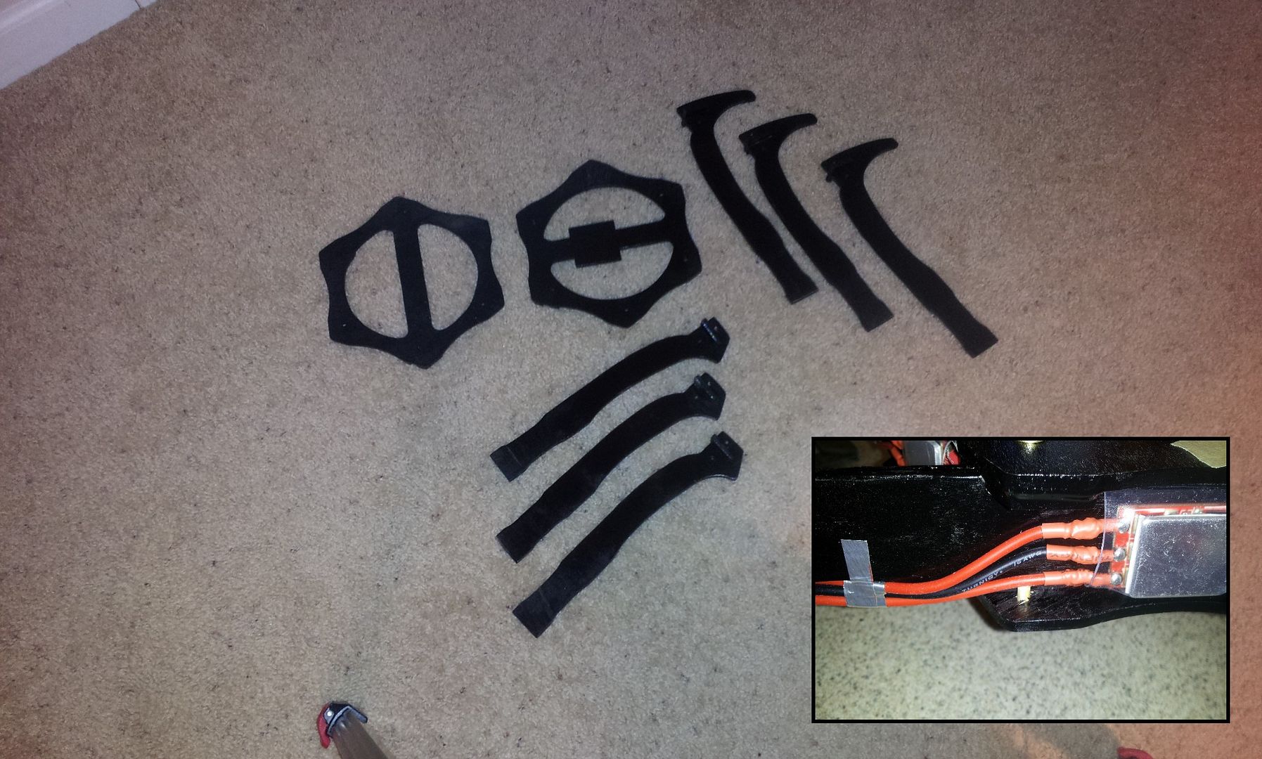
Last in the build was the organization of the wiring. Most important, this included stacking the motor wires under the 'trailing edge' of the booms. I also rounded the 'leading edge' or top of the boom to reduce the splash obstruction. I've yet to get the wiring 'looking good' along the trailing edge, but that will be done soon.
If this design proves itself, and so far it flies outstandingly well, I may remake it with 2.0 and 2.5mm G10. That would drop the frame weight by half, which is currently 415g (with screws). As is, the AUW is just under 1180g with 4S. So I suspect I could get a G10 hex of this configuration down to a AUW of around 925g. I would also fix the booms in place by incorporating the slot and tab technique used in most frame plate and boom designs. I almost did use such on this one, but wanted to retain a nice clean upper plate for esthetics and gluing blocks and guides were easier, faster and required less precision. And of course, making the boom even thinner would shave off another percent or so of thrust column obstruction, increasing the TCE that much more.
The final calculation tells me, while this hex has six booms, it has only 20% more planform obstruction in the thrust column as the already excellent thrust column efficient 10x10mm carbon fiber boom tricopter , and only ~75% of the splash obstruction.
And before someone mentions it, yes... I did strongly consider adding a raised mini bulge texture to the boom surface. The air velocity is high enough, as well there is enough vertical surface area to make it worthwhile. The technique I considered would have been laying a hex-shaped screen with openings of around 2mm across the flat of the boom, then buttering 15 minute epoxy across the screen. Waiting until the epoxy had set to a rather firm gummy consistency, then gently lifting off the screen. Allowing enough time to for the hex-shaped 'mounds' of epoxy to flow, round and harden to a nice mound. This uniform texture would improve the TCE by improving the boundary layer off the boom, as well as serve as the stiffener tube. This is something that would require extra effort, or similar could easily be done on the boom material itself during a mass produced manufacturing process.
My initial maiden was a crash. But purely because of my confusion. I connected everything up rather late one night and since the ESC power and control wiring 'appeared' to come from the end of the boom's motor, but because of the way the booms are inserted, (LOL even though I designed it) I inadvertently hooked them up offset by 60 degrees. It did this weird Euler's Disk thing and the flight lasted about a second.
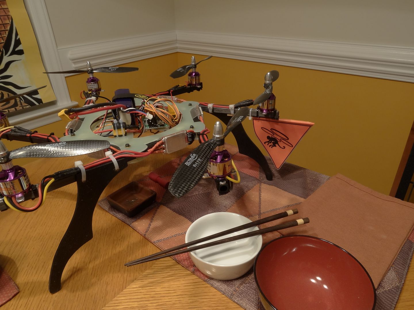
Of course, the most important feature is, how does it fly when properly connected? So far, better than I imagined! Rock solid and liquid smooth off of Steveis' stock setting of 1.11S2.
Please excuse the crude taping of the stacked motor leads on the trailing edge and the orange orientation tape. As to the slow fly props, I will switch to carbon fiber as my confidence grows flying it. I will also do a much better job of affixing the wires now that I know it flies great.
https://vimeo.com/89800473
https://vimeo.com/89814090
There’s been one aspect of all multirotors that has nagged me for some time.
And that is the insouciant concern for thrust column efficiency (TCE). Most builders take little notice of TCE, in that they design and build mostly for a handful of other reasons. Several commercial multirotors designers ignore this aspect as well. Many designers concern themselves with a single or combination of, initial cost, crash repair cost, crash management, size, weight, payload capacity, materials at hand, what they’ve seen before, etc. Rarely, if ever, is TCE even a consideration.
This is surprising in that low TCE can reduce flight time and lift capacity by as much as 25%. Most plate-type booms are in the neighborhood of 15%. Many configurations aggravate the TCE by placing the ESC flat, directly in the highest cross-section of thrust. Many place holes in the booms, however that most likely for weight reduction, and the result is turbulence, buying very little increased lift.
But to give credit where credit is due, clean carbon fiber round booms have outstanding TCE. But I suspect CF tubes are chosen mostly for weight/strength consideration. However, even square wood, aluminum or carbon fiber booms have decent efficiency. Square booms do have a maximum thrust splash area, in that the leading edge is flat, but since a square tube or solid boom has a relatively small planform area, the thrust splash does not move into a critical region of gross inefficiency overall. I have seen double plates turned vertical, but generally the boom has horizontal structure between the plates, such as screws, standoffs, etc., to improve rigidity.
So, setting aside those designs which are either excellent or passable in TCE, I want to experiment with a paradigm shifting idea. To step beyond even the round clean carbon fiber boom, and get the TCE as close to 100% as is possible, by turning the grossly inefficient common flat boom vertical.
The idea was sparked by my ‘Racing Quad’ design I did several months ago. It basically utilized a shallow chord airfoil shape as the booms. It then occurred to me, if the boom could be made stiff enough, a simple flat plate could be used and could be built much easier and cheaper. So I began to design from that aspect.
The following hexicopter is made from 3/16” plywood for the booms and 5/32” plywood for the main plates.
I started by designing my general idea in SketchUp, then tweaking and changing several times until I had a rough structure, then trimmed the main plate and booms down to a size that was not too overly bulky given I was using an average strength material. I then printed out the shapes and spray adhered them to the plywood and cut them out with a band saw.
I coated the area of most active boom flex with epoxy, essentially adding a ~0.6mm non-reinforced rigid membrane tube.
I made a common ring-type harness. All connections are splayed wire T interface connections with a fine copper wire wrapping, then soldered and double coated with epoxy.
I suspect the reason why this design has not been done before, (at least I have yet to see it) is the problematic mounting of the motors on a very thin vertical plate. My solution is straightforward and simple. I used interlocking pieces, wood glued the pieces and reinforced them with two coats of epoxy on the surface. I also did not use the cross piece to zip-tie the motors down. They are only for lateral support, so there is no constant upward pull, or jerk moments on the piece, only compression.
Mounting the vertical booms to the frame is easy. I made blocking tabs and guides at every other corner, and did the same on the opposing plate, offset by a corner, so all corners have blocking and guide rigidity either above or below.
The two halves apart that are pressed together and securely clamped with six screws.
The result is an amazingly strong and rigid six sided box structure that can withstand dozens of kilos of shear, trapezoidal force.
I’m also utilizing clear shrink as my ESC mounting material. I’ve indented the booms so that the shrink does not interfere with the clamp region near each fastener, and to allow higher PSI at the clamp points and to allow the shrink to move freely during the heating process.
I’ve recessed the KK2.1 ‘inside’ the ring for protection and also recessed it back, off center about 20mm, so the Invensense chip is as close to the center of lift and the CG as possible. The battery is mounted on top to put the elevation CG closer in-line with the lift plane. The result is the elevation CG is about 1cm below the lift plane. I mounted the Rx underneath since I used foil tape to afix the motor wires to the booms. Foil tape is extremely strong in uniform tension, but yields easily when tearing.
Next came some rattle-can black and putting it together. Both went fast. I was a little worried I would need three hands to wrestle to manipulate it all, but it went together much easier than I thought. Having a block and guide only on one surface at each corner allowed me to slide and rotate each boom into position easily. Another aspect of such a design is I can slightly rotate each boom a degree or so for perfect vertical alignment before clamping down hard with the screws. One post design change I made was adding small wood pins on the outside corner where the boom is merely clamped and not blocked. I added the pins as reassurance against a catastrophic mishap if the clamping screws worked loose. I will loctite them as well.
Last in the build was the organization of the wiring. Most important, this included stacking the motor wires under the 'trailing edge' of the booms. I also rounded the 'leading edge' or top of the boom to reduce the splash obstruction. I've yet to get the wiring 'looking good' along the trailing edge, but that will be done soon.
If this design proves itself, and so far it flies outstandingly well, I may remake it with 2.0 and 2.5mm G10. That would drop the frame weight by half, which is currently 415g (with screws). As is, the AUW is just under 1180g with 4S. So I suspect I could get a G10 hex of this configuration down to a AUW of around 925g. I would also fix the booms in place by incorporating the slot and tab technique used in most frame plate and boom designs. I almost did use such on this one, but wanted to retain a nice clean upper plate for esthetics and gluing blocks and guides were easier, faster and required less precision. And of course, making the boom even thinner would shave off another percent or so of thrust column obstruction, increasing the TCE that much more.
The final calculation tells me, while this hex has six booms, it has only 20% more planform obstruction in the thrust column as the already excellent thrust column efficient 10x10mm carbon fiber boom tricopter , and only ~75% of the splash obstruction.
And before someone mentions it, yes... I did strongly consider adding a raised mini bulge texture to the boom surface. The air velocity is high enough, as well there is enough vertical surface area to make it worthwhile. The technique I considered would have been laying a hex-shaped screen with openings of around 2mm across the flat of the boom, then buttering 15 minute epoxy across the screen. Waiting until the epoxy had set to a rather firm gummy consistency, then gently lifting off the screen. Allowing enough time to for the hex-shaped 'mounds' of epoxy to flow, round and harden to a nice mound. This uniform texture would improve the TCE by improving the boundary layer off the boom, as well as serve as the stiffener tube. This is something that would require extra effort, or similar could easily be done on the boom material itself during a mass produced manufacturing process.
My initial maiden was a crash. But purely because of my confusion. I connected everything up rather late one night and since the ESC power and control wiring 'appeared' to come from the end of the boom's motor, but because of the way the booms are inserted, (LOL even though I designed it) I inadvertently hooked them up offset by 60 degrees. It did this weird Euler's Disk thing and the flight lasted about a second.
Of course, the most important feature is, how does it fly when properly connected? So far, better than I imagined! Rock solid and liquid smooth off of Steveis' stock setting of 1.11S2.
Please excuse the crude taping of the stacked motor leads on the trailing edge and the orange orientation tape. As to the slow fly props, I will switch to carbon fiber as my confidence grows flying it. I will also do a much better job of affixing the wires now that I know it flies great.
https://vimeo.com/89800473
https://vimeo.com/89814090
"To learn who has no confidence in their convictions, simply find out who you are not allowed to criticize"
~Voltaire
-
Blunt Force Trauma
- Senior member
- Posts: 666
- Joined: Tue Jan 25, 2005 10:18 pm
- I've played Bz for: Forever
- Dm Strat or Missions: DM
- Location: North Carolina
Re: Commence Building
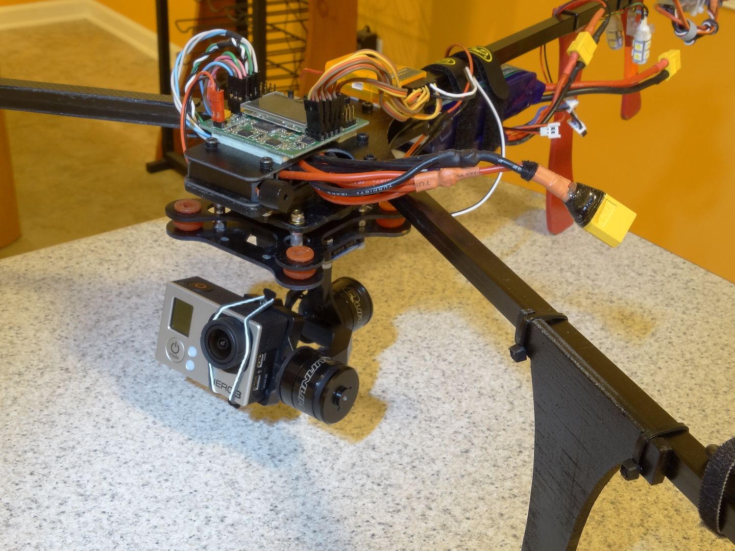
A quick addition. Bought a cheap 2-axis gimbal. Works decent. Flying FPV and the dog startles me .
https://vimeo.com/94899835
https://vimeo.com/94899835
"To learn who has no confidence in their convictions, simply find out who you are not allowed to criticize"
~Voltaire
-
BZROM
- Pilot
- Posts: 153
- Joined: Sun Dec 26, 2010 2:03 pm
- I've played Bz for: 15+
- Dm Strat or Missions: Strat
- Location: NC. USA
- Contact:

-
Blunt Force Trauma
- Senior member
- Posts: 666
- Joined: Tue Jan 25, 2005 10:18 pm
- I've played Bz for: Forever
- Dm Strat or Missions: DM
- Location: North Carolina
Re: Commence Building
Thanks BZROM
Haven't added in a while. I've built two more since I posted back in May.
One is a modification of my vertical boom hex. I was satisfied with the efficiency and performance of thin vertical booms, but was unhappy with the weight of using 5/32" plywood, so I disassembled it and re-built it re-using the wiring harness and using G10 and pultruded carbon fiber square tubes. Not thin vertical booms, but MUCH easier to build, weighs 180g less, coming in at just over 1kg (without battery) and is at least 50% stronger in the booms and 300% stronger at the main plates. I saved continuing the ultra efficient vertical booms for a mini quad.
It flies great.
https://vimeo.com/98086348
https://vimeo.com/98183977
--------------
Next, I continued with the ultra thin vertical boom theory and built a mini quad. Mini quads are extremely popular now because they can race through trees with less chance of impacting a tree, and when they do, the low mass keeps damage to a minimum. I used thin brass strips to carry the voltage across the booms to the motors to minimize the thrust obstruction. The boom are 2.93mm wide. I'm pretty sure I have the thinnest booms in planform yet seen on a multirotor of any size EVEN the popular micro quad, the ProtoX . . . The ProtoX has two booms per motor, one is 1.68mm, the other 1.5mm.
It's 100% 2mm carbon fiber plate. The frame weighs 136g.
https://vimeo.com/100373044
It has the control board, battery, ESCs and FPV camera all free-floating on a wrap-around cage.
Also I added tabs and a blunt and flat nose to carry my GoPro
One very unique thing I discovered building this mini and using very high KV motors of 2600rpm x 16.8V = 43,680rpm (at max theoretical rpm) is the cheap and flexible props I used to test out the first few flights, was the prop tips would flatten and resonate like a reed in a clarinet. The encased GoPro I used to record the sound you hear in the video does not do justice to how loud it is. It was reverberating throughout my yard and neighborhood.

https://vimeo.com/104200028
Once I put on stiffer glass-reinforced props, I traded the sound for pure acceleration. I'll try and get some video of its speed, but opening it up in my backyard without the video transmitter on it, making it a bit heavier. . . is it goes WAY too high and out of sight in literally a second and a half. More or less what is seen here..
Haven't added in a while. I've built two more since I posted back in May.
One is a modification of my vertical boom hex. I was satisfied with the efficiency and performance of thin vertical booms, but was unhappy with the weight of using 5/32" plywood, so I disassembled it and re-built it re-using the wiring harness and using G10 and pultruded carbon fiber square tubes. Not thin vertical booms, but MUCH easier to build, weighs 180g less, coming in at just over 1kg (without battery) and is at least 50% stronger in the booms and 300% stronger at the main plates. I saved continuing the ultra efficient vertical booms for a mini quad.
It flies great.
https://vimeo.com/98086348
https://vimeo.com/98183977
--------------
Next, I continued with the ultra thin vertical boom theory and built a mini quad. Mini quads are extremely popular now because they can race through trees with less chance of impacting a tree, and when they do, the low mass keeps damage to a minimum. I used thin brass strips to carry the voltage across the booms to the motors to minimize the thrust obstruction. The boom are 2.93mm wide. I'm pretty sure I have the thinnest booms in planform yet seen on a multirotor of any size EVEN the popular micro quad, the ProtoX . . .
It's 100% 2mm carbon fiber plate. The frame weighs 136g.
https://vimeo.com/100373044
It has the control board, battery, ESCs and FPV camera all free-floating on a wrap-around cage.
Also I added tabs and a blunt and flat nose to carry my GoPro
One very unique thing I discovered building this mini and using very high KV motors of 2600rpm x 16.8V = 43,680rpm (at max theoretical rpm) is the cheap and flexible props I used to test out the first few flights, was the prop tips would flatten and resonate like a reed in a clarinet. The encased GoPro I used to record the sound you hear in the video does not do justice to how loud it is. It was reverberating throughout my yard and neighborhood.
https://vimeo.com/104200028
Once I put on stiffer glass-reinforced props, I traded the sound for pure acceleration. I'll try and get some video of its speed, but opening it up in my backyard without the video transmitter on it, making it a bit heavier. . . is it goes WAY too high and out of sight in literally a second and a half. More or less what is seen here..
"To learn who has no confidence in their convictions, simply find out who you are not allowed to criticize"
~Voltaire
-
(GK)_Lil_Pain!

- In Training
- Posts: 18
- Joined: Wed Jun 15, 2011 9:03 am
- I've played Bz for: On/Off 6 years
- Dm Strat or Missions: Team DM
- Location: Savannah, Georgia
- Contact:
Re: Commence Building
Careful with those orange receivers. Their signal they get from the transmitter doesn't have a lot of range in the RC airplane world. Some of the clubs around our area have even banned them. Did you get most of your electronics from hobbyking?
-
Blunt Force Trauma
- Senior member
- Posts: 666
- Joined: Tue Jan 25, 2005 10:18 pm
- I've played Bz for: Forever
- Dm Strat or Missions: DM
- Location: North Carolina
Re: Commence Building
Yea, most is HK stuff. I also have a Spektrum AR8000, but have several Orange DSM2s and one Orange DSMX. They all have a range of at least 1500 feet with clear LOS, way more than enough for my MRs. Pretty much enough for FPV since my goggles and vid tx start going to static at around 1000 feet using circular polarized antennas.
My guess is the guys at your field might have been using DSM2 with a bunch of others. DSM2 doesn't play well with a dozen or more close to it. I usually fly by myself, or if I go to Dix Field in Raleigh, there may be ..maybe.. 8 others flying at any one time.
Here's a normal crowd I deal with. . .
https://vimeo.com/94899835#t=1m18s
"To learn who has no confidence in their convictions, simply find out who you are not allowed to criticize"
~Voltaire